


How does an incremental optical encoder ensure reliability against vibration and interference?
Release Time : 2026-02-19
In modern industrial automation systems, the incremental optical encoder, as a core sensor for position and velocity feedback, directly impacts the control accuracy and operational safety of the equipment. In applications such as CNC machine tools, elevators, and medical equipment, vibration and electromagnetic interference are ubiquitous, potentially leading to pulse signal loss, counting errors, or system malfunctions.
1. Reinforced Mechanical Structure: A Physical Barrier in Vibration Environments
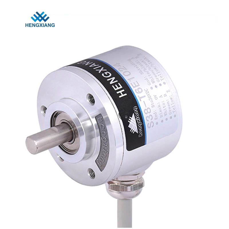
The vibration resistance of an incremental optical encoder stems primarily from its reinforced mechanical structure. Precision components within the encoder, such as the optical code disk, LEDs, and photodetectors, are comprehensively protected by a high-strength aluminum alloy housing. The housing utilizes an integrated casting process, eliminating seams and enhancing overall rigidity. The code disk shaft system employs a dual-bearing support structure, controlling axial and radial runout to the micrometer level, ensuring smooth rotation even under high-frequency vibration environments. Some high-end products also incorporate internal damping materials to absorb external vibration energy and prevent its transmission to the optical components.
2. Optimized Optical System: Ensuring Signal Source Stability
The core of a photoelectric encoder is its optical signal generation system. The LEDs employ a constant current drive circuit to ensure stable light intensity unaffected by power fluctuations. The photodetector uses a high-sensitivity, low-noise phototransistor, coupled with a precision optical lens, to focus light onto the code disk's engraved area, enhancing signal contrast. The code disk itself is made of glass or metal, with engraving precision reaching thousands to tens of thousands of pulses per revolution, resulting in clear, burr-free edges. Under vibration conditions, the stability of the optical system directly determines the quality of the pulse signal.
3. Circuit Anti-interference Design: Signal Purification in Electromagnetic Environments
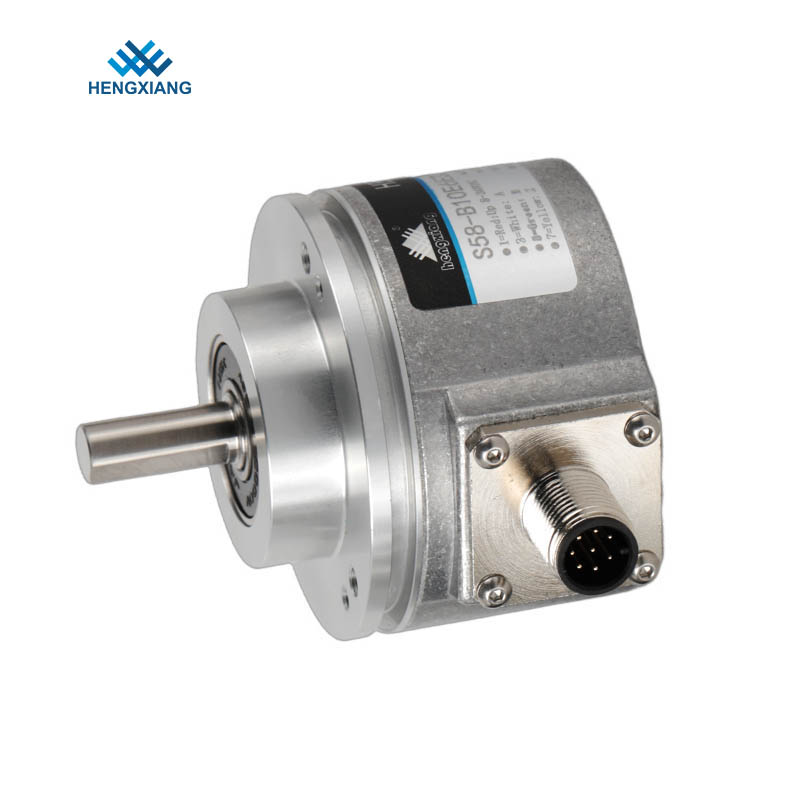
Industrial environments contain numerous sources of electromagnetic interference, such as frequency converters, servo drives, and relays, making encoder signal lines susceptible to coupling interference. The incremental optical encoder's circuit design employs a multi-layer shielding strategy. A differential drive chip is configured at the signal output end to convert single-ended signals into differential signals for transmission, effectively suppressing common-mode interference at the receiver. The cable uses twisted-pair shielded wire, with the shielding layer grounded at one end to prevent ground loop current from introducing noise. In terms of circuit board layout, analog and digital signals are arranged separately, power traces maintain a safe distance from signal traces, and a complete ground plane is provided below critical signal lines. Some products also integrate signal filtering circuits to hardware-filter high-frequency noise, ensuring steep, burr-free output pulse edges.
4. Environmental Protection Design: Long-Term Protection Under Harsh Conditions
Long-term operational reliability depends not only on vibration and interference resistance but also on environmental protection. Incremental optical encoders typically achieve IP65 or IP67 protection ratings, with O-ring seals at housing seams and labyrinth oil seals at shaft extensions to prevent dust, moisture, and oil from entering the interior. The operating temperature range covers -25℃ to +85℃, and electronic components are selected to industrial or automotive-grade specifications, ensuring no drift at high temperatures and no failure at low temperatures. In highly corrosive environments such as chemical and metallurgical industries, the housing surface can be anodized or sprayed to enhance chemical corrosion resistance. This comprehensive environmental protection design ensures that the encoder maintains stable performance under harsh conditions, with a service life of tens of thousands of hours.
The vibration and interference resistance design of incremental optical encoders is a comprehensive reflection of mechanical structure, optical system, circuit protection, and environmental adaptability. From housing reinforcement to differential signal transmission, from optical optimization to electromagnetic shielding, every detail is crucial to signal stability and system security. In today's increasingly sophisticated industrial automation, encoders are not only position sensors, but also the cornerstone of trust for the entire control system.
1. Reinforced Mechanical Structure: A Physical Barrier in Vibration Environments
The vibration resistance of an incremental optical encoder stems primarily from its reinforced mechanical structure. Precision components within the encoder, such as the optical code disk, LEDs, and photodetectors, are comprehensively protected by a high-strength aluminum alloy housing. The housing utilizes an integrated casting process, eliminating seams and enhancing overall rigidity. The code disk shaft system employs a dual-bearing support structure, controlling axial and radial runout to the micrometer level, ensuring smooth rotation even under high-frequency vibration environments. Some high-end products also incorporate internal damping materials to absorb external vibration energy and prevent its transmission to the optical components.
2. Optimized Optical System: Ensuring Signal Source Stability
The core of a photoelectric encoder is its optical signal generation system. The LEDs employ a constant current drive circuit to ensure stable light intensity unaffected by power fluctuations. The photodetector uses a high-sensitivity, low-noise phototransistor, coupled with a precision optical lens, to focus light onto the code disk's engraved area, enhancing signal contrast. The code disk itself is made of glass or metal, with engraving precision reaching thousands to tens of thousands of pulses per revolution, resulting in clear, burr-free edges. Under vibration conditions, the stability of the optical system directly determines the quality of the pulse signal.
3. Circuit Anti-interference Design: Signal Purification in Electromagnetic Environments
Industrial environments contain numerous sources of electromagnetic interference, such as frequency converters, servo drives, and relays, making encoder signal lines susceptible to coupling interference. The incremental optical encoder's circuit design employs a multi-layer shielding strategy. A differential drive chip is configured at the signal output end to convert single-ended signals into differential signals for transmission, effectively suppressing common-mode interference at the receiver. The cable uses twisted-pair shielded wire, with the shielding layer grounded at one end to prevent ground loop current from introducing noise. In terms of circuit board layout, analog and digital signals are arranged separately, power traces maintain a safe distance from signal traces, and a complete ground plane is provided below critical signal lines. Some products also integrate signal filtering circuits to hardware-filter high-frequency noise, ensuring steep, burr-free output pulse edges.
4. Environmental Protection Design: Long-Term Protection Under Harsh Conditions
Long-term operational reliability depends not only on vibration and interference resistance but also on environmental protection. Incremental optical encoders typically achieve IP65 or IP67 protection ratings, with O-ring seals at housing seams and labyrinth oil seals at shaft extensions to prevent dust, moisture, and oil from entering the interior. The operating temperature range covers -25℃ to +85℃, and electronic components are selected to industrial or automotive-grade specifications, ensuring no drift at high temperatures and no failure at low temperatures. In highly corrosive environments such as chemical and metallurgical industries, the housing surface can be anodized or sprayed to enhance chemical corrosion resistance. This comprehensive environmental protection design ensures that the encoder maintains stable performance under harsh conditions, with a service life of tens of thousands of hours.
The vibration and interference resistance design of incremental optical encoders is a comprehensive reflection of mechanical structure, optical system, circuit protection, and environmental adaptability. From housing reinforcement to differential signal transmission, from optical optimization to electromagnetic shielding, every detail is crucial to signal stability and system security. In today's increasingly sophisticated industrial automation, encoders are not only position sensors, but also the cornerstone of trust for the entire control system.