


How Do Incremental Signals from a Hollow Shaft Encoder Enable Precise Speed and Position Control?
Release Time : 2026-04-22
In the realm of industrial automation and precision motion control, the ability to accurately monitor the rotation of a motor shaft is paramount. The incremental optical encoder with a hollow shaft design has emerged as a critical component in this domain, bridging the gap between mechanical movement and digital control. Unlike solid shaft encoders that require complex couplings, the hollow shaft variety mounts directly onto the motor shaft, offering a compact and robust solution. This device transforms physical rotation into a series of electrical pulses, providing the necessary feedback for a control system to regulate speed and position with high fidelity.
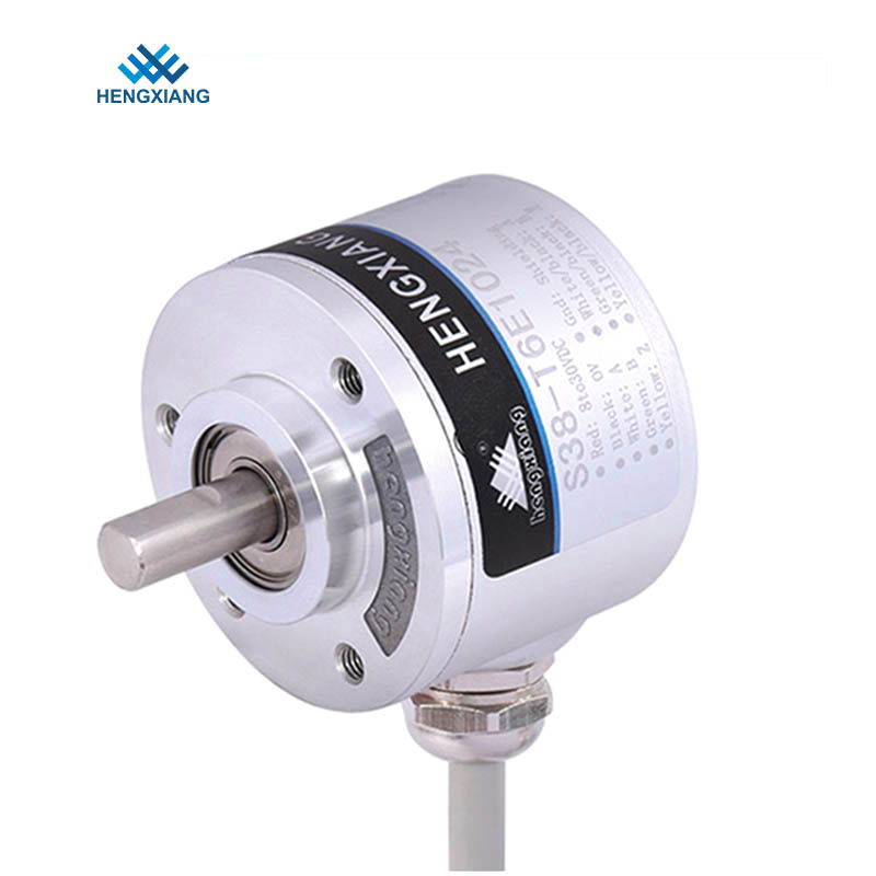
The core mechanism of an incremental optical encoder relies on a precisely etched glass or plastic code wheel attached to the rotating hollow shaft. As the shaft turns, this wheel spins between a light-emitting diode and a photodetector array. The code wheel features a pattern of opaque and transparent lines, often referred to as a grating. When light passes through the transparent sections, it strikes the photodetector, generating an electrical pulse. This process converts the continuous mechanical rotation into a discrete digital signal. The number of lines on the wheel determines the resolution, or Pulses Per Revolution (PPR), which dictates the granularity of the feedback provided to the controller.
Central to the functionality of the incremental encoder are the A and B output channels. These two channels produce square wave signals that are phase-shifted by 90 degrees relative to each other, a relationship known as quadrature. This phase shift is the key to determining the direction of rotation. If channel A leads channel B, the controller interprets the motion as clockwise; conversely, if channel B leads channel A, the motion is counter-clockwise. By monitoring the sequence of these rising and falling edges, the control system can instantly detect reversals in motion, which is essential for applications involving reciprocating movement or precise positioning.
To achieve high-resolution speed and position data, the controller utilizes a technique called quadrature decoding. Instead of counting only the rising edges of a single channel, the decoder counts both the rising and falling edges of both the A and B channels. This effectively multiplies the resolution of the encoder by a factor of four. For instance, an encoder with a physical resolution of 1,000 PPR can provide 4,000 distinct counts per revolution through this method. This interpolation allows for incredibly fine adjustments in speed control loops and precise positioning, enabling the motor to hold a specific angle or maintain a constant velocity even under varying load conditions.
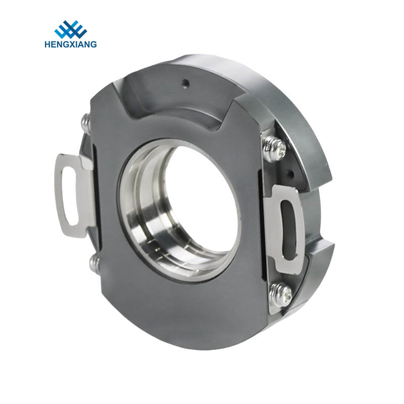
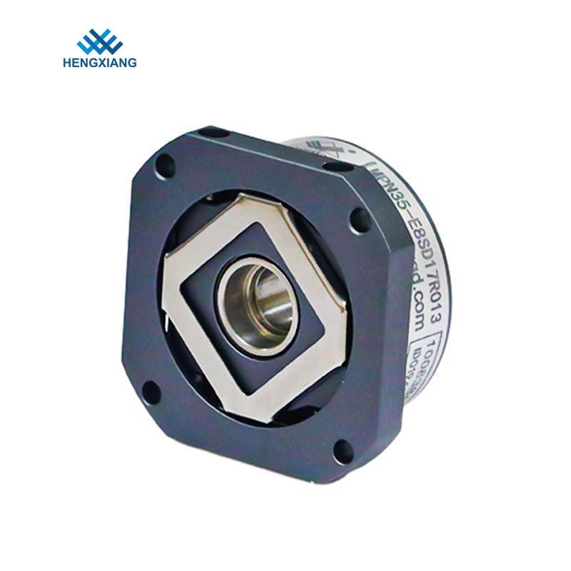
The hollow shaft design offers distinct advantages that enhance the reliability of this signal generation. By mounting directly onto the motor shaft using a spring-loaded stator or flexible coupling, the encoder eliminates the need for a separate flexible coupling. This direct connection minimizes mechanical backlash and reduces the overall length of the motor assembly. Furthermore, the hollow design isolates the sensitive internal bearings of the encoder from external axial and radial loads. This isolation ensures that the code wheel remains perfectly centered within the optical assembly, preventing signal jitter or loss of pulses that could occur if the shaft were subjected to mechanical stress.
In addition to direction and position, the frequency of the output pulses provides a direct measure of rotational speed. The control system, often a Variable Frequency Drive (VFD) or a servo amplifier, measures the time interval between pulses or counts the number of pulses over a fixed time period. This data is fed into a Proportional-Integral-Derivative (PID) control loop. If the actual speed derived from the encoder feedback deviates from the target speed, the PID algorithm adjusts the voltage and frequency supplied to the motor to correct the error. This closed-loop control ensures that the motor maintains a constant speed regardless of load fluctuations, which is critical in applications like conveyor belts or web handling.
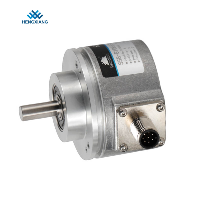
For absolute positioning within a single revolution, the incremental encoder typically includes a third channel known as the Z pulse or index pulse. This channel generates a single pulse once per revolution, occurring at a specific mechanical angle. The Z pulse serves as a reference point or "home" position for the system. Upon startup or after a power loss, the machine can rotate the shaft until it detects this index pulse, thereby synchronizing the digital count with the physical position of the load. This referencing capability is vital for ensuring that automated machinery starts its cycle from a known, repeatable location.
Signal integrity is maintained through the use of differential line drivers, typically adhering to the RS-422 standard. In electrically noisy industrial environments, electromagnetic interference can corrupt low-voltage signals. Differential signaling transmits the data on paired wires (A+ and A-, B+ and B-), where the receiver detects the voltage difference between the pair rather than the voltage relative to the ground. This method effectively cancels out common-mode noise, ensuring that the pulse train arriving at the controller is clean and free from spurious counts. This reliability is essential for maintaining precision over long cable runs.
Ultimately, the incremental hollow shaft encoder acts as the eyes of the motion control system. By providing a continuous stream of high-frequency digital pulses that encode direction, speed, and relative position, it allows the controller to make real-time adjustments to the motor's behavior. The combination of optical precision, quadrature signal processing, and the mechanical robustness of the hollow shaft design makes this device an indispensable tool for achieving the high efficiency and accuracy demanded by modern industrial automation.
The core mechanism of an incremental optical encoder relies on a precisely etched glass or plastic code wheel attached to the rotating hollow shaft. As the shaft turns, this wheel spins between a light-emitting diode and a photodetector array. The code wheel features a pattern of opaque and transparent lines, often referred to as a grating. When light passes through the transparent sections, it strikes the photodetector, generating an electrical pulse. This process converts the continuous mechanical rotation into a discrete digital signal. The number of lines on the wheel determines the resolution, or Pulses Per Revolution (PPR), which dictates the granularity of the feedback provided to the controller.
Central to the functionality of the incremental encoder are the A and B output channels. These two channels produce square wave signals that are phase-shifted by 90 degrees relative to each other, a relationship known as quadrature. This phase shift is the key to determining the direction of rotation. If channel A leads channel B, the controller interprets the motion as clockwise; conversely, if channel B leads channel A, the motion is counter-clockwise. By monitoring the sequence of these rising and falling edges, the control system can instantly detect reversals in motion, which is essential for applications involving reciprocating movement or precise positioning.
To achieve high-resolution speed and position data, the controller utilizes a technique called quadrature decoding. Instead of counting only the rising edges of a single channel, the decoder counts both the rising and falling edges of both the A and B channels. This effectively multiplies the resolution of the encoder by a factor of four. For instance, an encoder with a physical resolution of 1,000 PPR can provide 4,000 distinct counts per revolution through this method. This interpolation allows for incredibly fine adjustments in speed control loops and precise positioning, enabling the motor to hold a specific angle or maintain a constant velocity even under varying load conditions.
The hollow shaft design offers distinct advantages that enhance the reliability of this signal generation. By mounting directly onto the motor shaft using a spring-loaded stator or flexible coupling, the encoder eliminates the need for a separate flexible coupling. This direct connection minimizes mechanical backlash and reduces the overall length of the motor assembly. Furthermore, the hollow design isolates the sensitive internal bearings of the encoder from external axial and radial loads. This isolation ensures that the code wheel remains perfectly centered within the optical assembly, preventing signal jitter or loss of pulses that could occur if the shaft were subjected to mechanical stress.
In addition to direction and position, the frequency of the output pulses provides a direct measure of rotational speed. The control system, often a Variable Frequency Drive (VFD) or a servo amplifier, measures the time interval between pulses or counts the number of pulses over a fixed time period. This data is fed into a Proportional-Integral-Derivative (PID) control loop. If the actual speed derived from the encoder feedback deviates from the target speed, the PID algorithm adjusts the voltage and frequency supplied to the motor to correct the error. This closed-loop control ensures that the motor maintains a constant speed regardless of load fluctuations, which is critical in applications like conveyor belts or web handling.
For absolute positioning within a single revolution, the incremental encoder typically includes a third channel known as the Z pulse or index pulse. This channel generates a single pulse once per revolution, occurring at a specific mechanical angle. The Z pulse serves as a reference point or "home" position for the system. Upon startup or after a power loss, the machine can rotate the shaft until it detects this index pulse, thereby synchronizing the digital count with the physical position of the load. This referencing capability is vital for ensuring that automated machinery starts its cycle from a known, repeatable location.
Signal integrity is maintained through the use of differential line drivers, typically adhering to the RS-422 standard. In electrically noisy industrial environments, electromagnetic interference can corrupt low-voltage signals. Differential signaling transmits the data on paired wires (A+ and A-, B+ and B-), where the receiver detects the voltage difference between the pair rather than the voltage relative to the ground. This method effectively cancels out common-mode noise, ensuring that the pulse train arriving at the controller is clean and free from spurious counts. This reliability is essential for maintaining precision over long cable runs.
Ultimately, the incremental hollow shaft encoder acts as the eyes of the motion control system. By providing a continuous stream of high-frequency digital pulses that encode direction, speed, and relative position, it allows the controller to make real-time adjustments to the motor's behavior. The combination of optical precision, quadrature signal processing, and the mechanical robustness of the hollow shaft design makes this device an indispensable tool for achieving the high efficiency and accuracy demanded by modern industrial automation.