


How to avoid signal attenuation when the transmission distance of an incremental linear encoder is extended?
Release Time : 2026-01-09
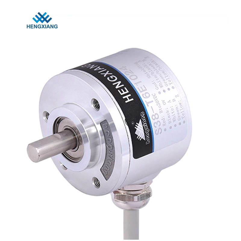
As a precision measuring device, the extended signal transmission distance of an incremental linear encoder must balance anti-interference capability and signal integrity; otherwise, attenuation can easily lead to counting errors or system malfunction. In industrial scenarios, the encoder's output pulse signal has a high frequency and steep edges, making it susceptible to cable resistance, capacitance, and electromagnetic interference during long-distance transmission, causing waveform distortion or even signal loss. Therefore, comprehensive optimization from multiple dimensions, including hardware selection, signal processing, wiring specifications, and auxiliary technologies, is necessary to ensure stable signal transmission.
Cable selection is fundamental to extending transmission distance. Incremental linear encoders typically use differential signal output, such as the RS-422 standard. Such signals require transmission through cables with matched characteristic impedance. Ordinary cables are prone to signal reflection due to impedance discontinuities, while dedicated twisted-pair shielded cables (STP) can effectively suppress common-mode interference. For ultra-long-distance transmission, low-capacitance cables should be selected to reduce signal attenuation, while ensuring sufficient wire diameter (e.g., AWG24 or higher) to reduce resistance loss. A double-layer shielding structure (aluminum foil + braided mesh) further enhances anti-electromagnetic interference capability, making it particularly suitable for high-interference environments such as those with frequency converters and motors.
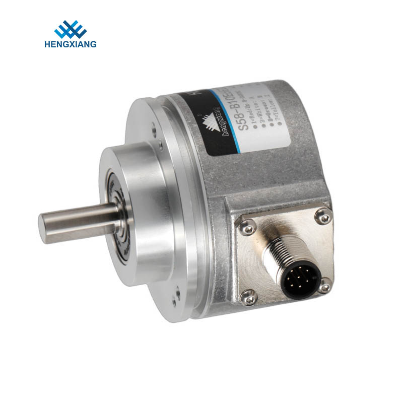
Impedance matching and terminating resistors are key technical aspects. Differential signal transmission requires consistent line impedance, typically 100-120Ω characteristic impedance. If the transmission distance exceeds 10 meters, a terminating resistor must be connected in parallel at the receiving end to eliminate reflected waves and prevent signal superposition leading to false counting. For example, an RS-422 interface requires a 120Ω terminating resistor at the controller end to ensure signal waveform stability. Furthermore, industrial-grade connectors must be used to ensure reliable contact and maintain shielding continuity, preventing noise introduction due to poor contact.
Signal repeater and drive enhancement technologies can overcome transmission limits. When the distance exceeds 50 meters, simple cable optimization is insufficient; signal repeaters or line drivers must be introduced. Repeaters amplify and shape signals, compensating for transmission losses and enabling multi-stage cascading to extend the transmission distance. Some high-end encoders have built-in differential drive circuits, directly supporting stable transmission over hundreds of meters. For example, an absolute encoder using the EnDat 2.5 protocol can transmit a 10MHz clock frequency signal 100 meters away via line drive output while maintaining a low bit error rate.
Wiring specifications and shielding/grounding strategies directly impact interference immunity. Encoder cables must be kept away from strong interference sources such as power lines and inverter output lines. If crossing is unavoidable, they should cross perpendicularly at 90° with a spacing of at least 30cm, or be isolated using metal partitions. The shielding layer should follow the "single-point grounding" principle, typically grounding at the controller end and leaving the encoder end suspended or grounded through a capacitor to avoid introducing common-mode noise via ground loops. In mobile applications (such as cable chain systems), highly flexible dedicated cables must be selected to ensure signal integrity after millions of bends.
Environmental adaptability design is crucial for ensuring long-term stability. Temperature fluctuations cause changes in cable resistance, affecting signal amplitude; therefore, materials with low temperature coefficients must be selected. In high-humidity environments, waterproof joints and sealed connectors are required to prevent moisture intrusion and short circuits. For equipment subject to severe vibration, cable fixing points must be reinforced to prevent loosening or cable breakage due to mechanical stress.
Software filtering and signal processing techniques can improve system fault tolerance. At the controller end, high-frequency noise can be eliminated through digital filtering algorithms (such as moving average and median filtering), while adaptive control algorithms dynamically adjust the sampling threshold to adapt to changes in signal strength. Some encoders support output signal frequency division, down-converting high-frequency signals before transmission, significantly reducing the bandwidth requirements.
Regular maintenance and condition monitoring are effective means of preventing failures. Encoder health records should be established, recording transmission distance, environmental parameters, and historical fault information. Regularly monitoring signal waveforms with an oscilloscope to analyze attenuation trends allows for the timely replacement of aging cables or adjustment of repeater positions. Furthermore, employing redundant transmission designs (such as dual-link backup) can further improve system reliability and ensure uninterrupted operation of critical equipment.